Overview & Applications
The 132kW Tunnel Construction Temporary Axial Flow Ventilation Fan is a high-efficiency, energy-saving axial fan specifically designed for tunnel and underground construction ventilation. It features a **counter-rotating double-stage impeller structure**, where two special motors equipped with imported bearings directly drive two impellers rotating in opposite directions. The two stages serve as guide vanes for each other, eliminating the need for stationary guide vanes found in conventional fans, resulting in a more compact structure and lower energy loss.
This fan is primarily used in high-speed railway, highway, railway tunnels, water conveyance tunnels, metal mines, and other underground projects. It delivers fresh air to the tunnel face via ducting for forced ventilation. The fan can handle air temperatures up to 80°C and is not suitable for corrosive gases. The **2×132kW configuration** (i.e., two 132kW motors combined) is a high-power variant within the SDF series – for example, the SDF(B)-4-No13 model has a maximum motor rating of 132×2 kW.
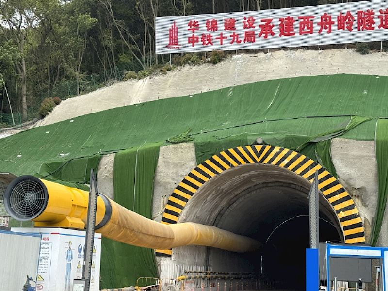
In **temporary ventilation** scenarios, the fan can be quickly installed at the tunnel portal or an inclined shaft, pushing fresh air to the working face through flexible ducts, while jet fans assist in exhausting contaminated air. In practice, two 132kW fans are often used in parallel with φ1.5m dual-resistant ducts (flame‑retardant and anti‑static) to deliver fresh air to the main tunnel face. As the tunnel advances, variable frequency drives or staged operation allow flexible airflow adjustment to meet ventilation demands at different construction stages.
| Air Volume |
3100m³/min |
| Pressure |
4550Pa |
Product Features
**1. Counter‑rotating design for high efficiency**
The innovative counter‑rotating impeller structure eliminates stationary guide vanes, reducing energy loss. The impellers use **high‑strength cast aluminum alloy blades** (some models feature airfoil‑shaped blades) with three‑dimensional twist design, offering three times the strength of ordinary steel blades. Efficiency is improved by 5%–10%, while noise is reduced by 10–20 dB(A).
**2. High pressure and large airflow for long‑distance ventilation**
High outlet velocity and pressure enable the fan to overcome duct resistance and deliver fresh air over long distances. The SDF(B)-4-No13 model delivers an airflow range of 1,695–3,300 m³/min and a pressure range of 930–5,920 Pa, with an efficient operating point at 2,691 m³/min. In projects like the Taihang Mountain Tunnel, 2×132kW fans with φ1.5m ducts successfully achieved long‑distance single‑head forced ventilation.
**3. Flexible staged or full operation for energy savings**
Depending on tunnel length and ventilation requirements, the fan can be used as a whole (both stages) or separately (one stage) to reduce energy consumption. Some models are available with two‑speed or three‑speed motors, allowing adjustable airflow and pressure as the tunnel advances – truly “on‑demand ventilation” that significantly saves electricity.
**4. Compact structure for easy installation and maintenance**
The fan consists of an air collector, first‑stage unit, second‑stage unit, motors, silencer, and duct connection. The steel plate housing, direct drive between motors and impellers, and simple overall construction make it robust, safe, and easy to maintain. Designed service life is no less than 20 years.
**5. Low noise for improved working environment**
Optimized aerodynamic design and noise reduction features keep noise levels low. SDF series low‑noise tunnel fans have been widely used in tunnel projects worldwide.
**6. VFD‑ready for intelligent control**
The fan can be paired with a variable frequency drive (VFD) to adjust speed according to actual ventilation demand at different construction stages, achieving 30%–50% energy savings. ABB and other VFD brands offer special optimization for tunnel ventilation fans. The control cabinet can include phase loss, open phase, and overload protection.
**7. Optional booster/relay operation**
By adding a reducer at the fan inlet, it can be connected to another fan in series for long‑distance tunnel relay ventilation, further improving performance.
FAQ
**Q1: Why is the fan power often written as “2×132kW” when it’s called a 132kW fan?**
A: The SDF series has a counter‑rotating double‑stage structure with two motors – one driving the first stage impeller and the other the second stage. “2×132kW” means each motor is 132kW, for a total installed power of 264kW. The SDF(B)-4-No13 is a typical example.
**Q2: How do I select the right fan based on tunnel length?**
A: Selection should consider tunnel length, cross‑sectional area, number of workers, and harmful gas emissions. The rated airflow should be 1.1–1.2 times the calculated requirement to account for leakage and losses. For long tunnels (≥2,000 m), large‑diameter ducts (e.g., φ1.5m or larger) are preferred to reduce resistance, and staged or relay ventilation may be necessary.
**Q3: How do I match the fan with the ventilation duct?**
A: The fan outlet diameter and duct diameter should be the same or smoothly transitioned via a reducer, with a difference no greater than 10%. Large‑diameter ducts are recommended to reduce air velocity and friction losses, saving energy – for a 1,000 m tunnel, increasing duct diameter from 0.6 m to 0.8 m can reduce power consumption by over 70%.
**Q4: How should the temporary ventilation fan be arranged in tunnel construction?**
A: The axial fan is typically installed at the tunnel portal or inclined shaft, pushing fresh air through a flexible duct to the face. Jet fans are placed inside the tunnel to induce and accelerate exhaust airflow. The fan axis should be parallel to the tunnel centreline and not intrude into the tunnel clearance envelope.
**Q5: Are there special requirements for using the fan in a gas‑rich tunnel?**
A: In gas tunnels, continuous ventilation must be maintained, and ducts must be flame‑retardant and anti‑static. If ventilation stops due to maintenance or power failure, personnel must be evacuated and power cut. The motor protection rating should be at least IP55, with insulation class F or higher.
**Q6: How does a VFD achieve energy savings?**
A: In early excavation stages, ventilation distance is short and required pressure is low – the VFD reduces fan speed to save energy. As the tunnel advances, speed is gradually increased to raise airflow and pressure. VFD control typically saves 30%–50% energy, avoiding the inefficiency of “a big horse pulling a small cart.”
---
Let me know if you need a different format (e.g., bullet points only, shorter version, or ready‑to‑print brochure style).


